
Introduction: The Real Cost of a Wrong Choice
HCl absorption system design is the engineering discipline of turning hydrogen chloride gas into recoverable hydrochloric acid instead of neutralizing it as waste. The job looks simple on paper — HCl is one of the most water-soluble gases there is — but it is heat, not solubility, that decides whether you recover a sellable 35–37% acid or watch your product strength and tail-gas compliance collapse in a single hot shift.
Here is the trap we keep seeing. An EPC team delivers a perfectly balanced HCl absorption system design for a chlorination off-gas: 1,000 kg/h of HCl, 35% acid out, tail gas under the limit. On paper, every number closes. Then a downstream reactor upsets and the feed swings from a calm 25% HCl to 42% in a single hour. The absorber — a simple packed tower spec’d for the calm case — overheats, the product acid drops to 26%, and the tail-gas scrubber starts riding the OSHA ceiling. Nobody changed the chemistry. The “steady-state” design simply had no margin for the one thing real plants do: swing.
This guide covers the operating envelope, not a single point. We walk through why HCl behaves the way it does, how a falling film absorber works, when a packed tower wins instead, the sizing parameters that matter, materials, tail-gas integration, the seven mistakes that sink first drafts, and a sizing checklist you can hand to a vendor. If you are still mapping the mass-transfer fundamentals, our primer on how a wet scrubber works covers the backbone this article builds on.
Key takeaways – HCl releases roughly 2,000 kJ/kg when absorbed — cooling, not just contact, is what makes concentrated acid possible. – Feed above ~20–30% HCl needs an isothermal, shell-side-cooled falling film absorber to reach ~35–37% w/w. – Impervious graphite is the default for hot, concentrated acid; PP and PVDF suit dilute, cooler duty. – A secondary tail scrubber is normally required to stay under the 5 ppm OSHA ceiling. – One disturbed operating point can collapse the whole design — size for the swing, not the snapshot.
1. Why HCl Is a Special Case for Gas Absorption
High solubility paired with intense heat (~2,000 kJ/kg)
HCl dissolves in water almost greedily. One volume of water takes up several hundred volumes of HCl at ambient temperature (see the NIST properties of hydrogen chloride). Its extreme solubility is dominated by chemical ionization rather than simple physical dissolution, which is why you cannot describe it with an ordinary Henry’s law constant — the relationship is covered in detail in these Henry’s law fundamentals on gas solubility.
The catch is the enthalpy of solution: roughly 2,000 kJ per kilogram of HCl absorbed, about −75 kJ per mole. That is not a footnote — it is the design. A 1,000 kg/h stream releases about 2,000,000 kJ/h, or roughly 560 kW of continuous heat, just from dissolution. Ignore it and your column runs hot, the liquor boils locally, and your absorber quietly becomes a stripper.
Why high concentration demands isothermal operation
The solubility of HCl barely drops with temperature, but the vapor pressure above the liquor rises sharply as it warms — so warm acid holds less HCl at the interface, and what you already absorbed starts to escape back into the gas. To make strong, reusable acid you must pull the heat out as fast as it forms.
That is the difference between “absorbing HCl” and “producing hydrochloric acid.” The first is a scrubbing job; the second is a heat-management job. And it is exactly what a falling film absorber — and any sound HCl absorption system design for strong acid — is built to do.
Industrial concentrated hydrochloric acid tops out around 35–37% w/w at ambient conditions. That plateau is an equilibrium solubility limit of the HCl–water system, not a number you beat by stacking more tubes or running the tower hotter.
2. What Is a Falling Film Absorber?
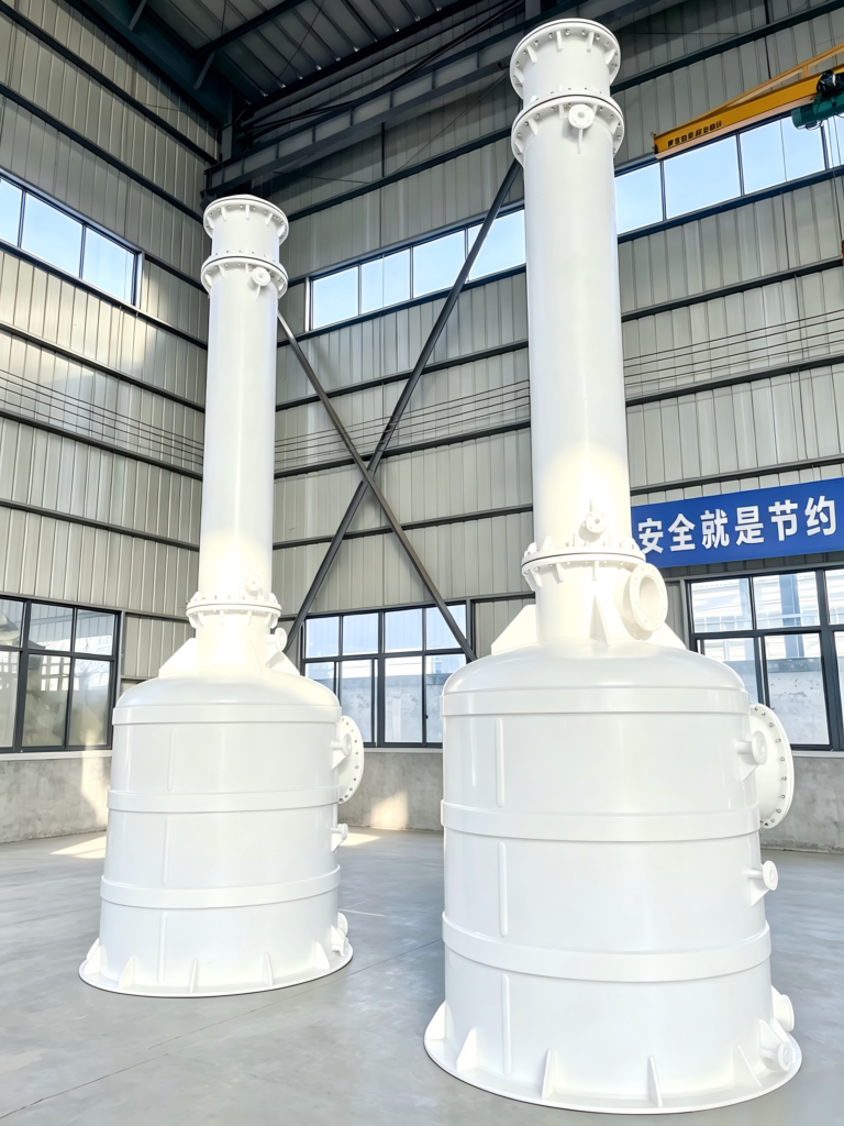
A falling film absorber is a vertical shell-and-tube exchanger: HCl gas and water (or weak acid) form a thin film flowing downward along the tube walls while cooling water circulates on the shell side, so absorption and heat removal happen in the same pass.
Shell-and-tube, in one paragraph
Picture a bundle of vertical tubes. Weak liquor is distributed evenly and spreads into a film a fraction of a millimeter thick on each wall, while cooling water runs in the shell. HCl gas enters at the top and travels down with the film (co-current, downward), dissolving and releasing heat; the tube wall and shell-side water remove that heat instantly for isothermal absorption. Acid made and heat removed in one pass.
For the construction detail, our page on the falling film absorption tower walks through the typical mechanical envelope and the options that matter for HCl service.
Falling film vs packed tower, in one line
A falling film absorber cools while it absorbs; a packed tower (also called a packed column) mostly absorbs and hopes the liquid stays cool on the way down.
3. How a Falling Film Absorber Works (Step by Step)
What makes the falling film geometry special is pairing a thin liquid film with immediate, continuous cooling. The short diffusion path keeps mass transfer fast, and the shell-side water keeps the interface cold so the local HCl vapor pressure stays low and more gas keeps dissolving. That pairing is the whole reason the unit climbs to commercial acid strength without boiling itself apart.
- Liquid distribution. Weak acid or water is metered to a top distributor that wets every tube evenly. A dry streak is a lost streak, because an unwetted wall neither absorbs nor cools.
- Film formation. Liquid forms a thin film on the tube wall, giving a short diffusion path and fast mass transfer.
- Co-current downward flow. Gas and liquid move down together, tolerating high velocities without flooding and keeping the driving force high at the inlet.
- Isothermal absorption. Heat at the film passes through the tube wall into shell-side cooling water, so temperature stays near the coolant and concentration climbs.
- Tail gas exit. The bottom stream is mostly inert gas plus a small HCl residual, sent on to a secondary scrubber.
- Closed-loop reflux. Product acid is collected; part recycles to the distributor to steady strength and the wetting rate.
4. Falling Film Absorber vs Packed Tower: Which to Choose
This is the decision that drives the whole HCl absorption system design.
Choose a falling film absorber when: – You must make commercial-grade acid (industry-typical upper limit ~35–37% w/w) – Feed HCl concentration is high, roughly above 20–30% in the gas – The duty is strongly exothermic and you cannot let it warm up
Choose a packed-bed / spray tower scrubber when: – The goal is emission control: knock HCl out of a vent to permit levels – Feed is dilute, or you are neutralizing and discharging – Capital simplicity beats recovered-acid value
| Factor | Falling film absorber | Packed / spray tower |
|---|---|---|
| Best duty | Strong acid recovery, high load | Dilute vent scrubbing, neutralization |
| Cooling method | Integral shell-side cooling | Limited; liquid heats as it falls |
| Max acid strength | ~35–37% w/w | Low; usually weak or neutralized |
| Gas concentration fit | High (>20–30%) | Low / variable |
| Pressure drop | Low (co-current flow) | Higher flooding risk |
| Capital cost | Higher | Lower |
| If mis-selected | Over-built, costly | Too hot, low strength, non-compliant |
For dilute ventilation and neutralization duty, our packed-bed / spray tower scrubber selection guide walks the trade-offs in detail.
5. Key Design Parameters for HCl Absorption System Design
Film thickness and tube wall wetting
You want the film thin but complete. Too thin invites dry patches; too thick slows mass transfer. The distributor and tube count set the wetting rate you specify — not the one you hope for.
Gas and liquid flow, and the L/G ratio
The liquid-to-gas ratio decides how much acid you make per pass and how low the tail goes. Too little liquid and you cannot carry the load; too much and you waste pumping and dilute the product. This ratio sits at the heart of every HCl absorption system design.
Temperature and cooling water duty
This is where most designs live or die. Cooling water flow, inlet temperature, and approach temperature set your maximum acid strength, so size the cooler for the full ~2,000 kJ/kg load plus a margin for upset.
Another pattern that bites teams: a plant sizes cooling water from the annual average, forgetting that late-summer return runs warmer. On the hottest week the product acid slips from 35% to 31% — and the fix, a slightly larger cooler, costs far less than a whole summer of lost grade. Always size for the warmest coolant you will actually see, not the springtime number.
Absorbent concentration and product acid strength
Fresh water makes the strongest acid fastest, but recycling weak acid helps control strength and wetting. Commercial HCl tops out around 35–37% w/w at ambient conditions, the practical solubility ceiling set by HCl–water equilibrium. Using recovered acid as the absorbent is common; it trims the make-up demand and keeps the circuit closed.
Pressure drop
Falling film units run with low pressure drop because co-current flow resists flooding, so specify the allowable ΔP for the distributor and gas routing. Low ΔP matters when HCl comes off a reactor at fixed backpressure — a choked absorber can back up the whole upstream unit.
6. Material Selection: Graphite, PP, PVDF, and Beyond
Impervious graphite is the workhorse for strong HCl: it conducts heat well for integral cooling and resists HCl across the range. It is the standard for concentrated-acid units.
Polypropylene (PP) and PVDF are the economical choice for dilute, lower-temperature duty. They resist HCl but conduct heat poorly, so keep them for weak acid at gentle temperature.
Tantalum resists HCl superbly but costs accordingly, so it enters only for special cases such as aggressive impurities or mixed streams where few other materials survive. Ordinary stainless steel and carbon steel do not resist HCl and are ruled out.
Pick the material to the product strength and temperature: graphite for a concentrated, warm stream; PP or PVDF for a cool, dilute vent.
7. System Integration: Tail-Gas & Closed-Loop Design
A falling film absorber is rarely the whole story. The tail gas still carries residual HCl, and the OSHA permissible exposure limit for hydrogen chloride is 5 ppm (ceiling). You do not get to “almost” meet that.
So you add a secondary tail-gas scrubber, often a small packed or venturi unit with water or dilute caustic (NaOH). Caustic adds margin and converts the residual to an easy-to-handle salt, which simplifies disposal and tightening the loop. Water alone can work for milder duties, but it leaves you managing a weak acid stream.
Closed-loop design matters: recycle weak acid to steady wetting and strength, and balance make-up with bleed so you do not flood the neutralization train. For a complete package, our complete acid gas scrubbing system integrates the absorber, tail scrubber, and controls as one validated skid.
The failure mode we see most: a plant commissions a falling film absorber, hits spec, and assumes the tail is fine. Then a warm afternoon lifts cooling-water temperature a few degrees, the absorber runs a touch hotter, and the stack crosses 5 ppm for the first time in months. The fix — a secondary scrubber — was deferred to “phase two” and never came.
8. Typical HCl Recovery Process Configurations
A few hydrochloric acid recovery system layouts show up repeatedly in practice:
- Single-stage falling film. One absorber, one cooler, one tail scrubber — good for moderate loads and where ~30% acid is acceptable.
- Multi-stage / series falling film. Two absorbers in series, progressively cooler, pushing toward the ~35–37% upper limit when grade drives the economics.
- Falling film + foam tower (or packed) in series. The falling film makes the bulk strong acid; a downstream tower polishes the tail for both high product and very low emission.
Choosing among these is the last step, once you have fixed the feed, the target acid, and the emission limit.
HCl absorption systems must meet different emission limits depending on where you operate. For the complete picture on VOC emission standards by region — including EU BAT-AELs, US NESHAP DRE, and China GB caps for pharma and chemicals — see our 2026 compliance guide.
9. 7 Common HCl Falling Film Absorber Design Mistakes
- Uneven liquid distribution. A distributor wetting 90% of tubes wastes 10% of capacity and invites hot spots. Get distribution right first.
- Under-sized cooling duty. Sizing the cooler for steady state and ignoring upset means the plant runs hot. Add margin for the peak rate and the ~2,000 kJ/kg load.
- Ignoring the tail gas. “The absorber handles it” is a bet you lose at 5 ppm. Design the secondary scrubber up front.
- Wrong material. PP where graphite belongs, or a metal HCl eats. Match material to strength and temperature.
- No turndown or operating flexibility. Plants swing; a unit that only works at nameplate flow fails when demand dips 30%.
- No safety margin on strength. Designing for exactly 37% leaves zero room for a warm coolant day. Target a bit under the limit.
- Choosing the wrong technology. A packed tower for strong-acid recovery, or a falling film for a dilute vent, guarantees disappointment. Let the job pick the machine.
10. What Data to Specify for Your HCl Absorption System Design
To get a real quote instead of a guess, your HCl absorption system design inquiry should carry:
- Gas flow: kg/h, and the operating range — not just the peak.
- Composition: HCl concentration plus the inerts and any impurities (they change materials and the tail design).
- Utilities: cooling water temperature and flow available, power, drainage.
- Emission limit: your permitted HCl at stack, and the monitoring basis.
- Product target: desired acid strength and whether you will reuse or neutralize.
Hand that to a vendor and you get a sized unit, not a catalog number. Our custom engineering & sizing services turn this data into a layout and a quote.
11. Real-World Case Study (Illustrative)
The following is an industry-typical example, illustrative only. It describes a common configuration and the reasoning behind it; it is not a specific customer, project, or measured result, and no project figures are cited.
A chlorination operator needed a hydrochloric acid recovery system from a byproduct gas stream instead of neutralizing and dumping it. The gas carried HCl at a high concentration — well above the ~20–30% threshold where a falling film absorber becomes the right tool — with mostly inert ballast.
They installed a single falling film absorber with integral graphite cooling, fed with weakly recirculated acid plus make-up water, targeting an industry-typical product of about 33–35% w/w. A secondary packed scrubber on caustic held the tail under 5 ppm, and cooling water was specified for the full load plus margin so a modest summer rise did not drop the grade.
In this illustrative layout the outcome was reusable acid instead of neutralized waste, with the tail comfortably inside permit.
Think your byproduct stream fits this pattern? Send us your gas composition and flow, and we will tell you whether a single-stage falling film, a series, or a hybrid is the right HCl absorption system design for you.
12. Frequently Asked Questions
Q: What is the maximum HCl concentration you can reach by absorption?
A: In practice, about 35–37% w/w at ambient pressure and temperature. That is the saturation ceiling from HCl–water equilibrium; above it you need different chemistry or elevated pressure.
Q: Can a falling film absorber handle inert gases?
A: Yes. Inerts such as air or nitrogen pass through with the tail gas. Size the unit for the HCl load and design the tail scrubber for the residual.
Q: PP or graphite: which should I choose?
A: Graphite for strong, warm HCl and integral cooling; PP or PVDF for dilute, cooler scrubbing duty where heat removal is modest. Match the material to product strength and temperature.
Q: Isothermal or adiabatic absorption: what is the difference?
A: Isothermal (falling film) removes heat as it forms, so you make strong acid. Adiabatic (most packed towers) lets the liquor warm, capping strength and favoring emission control over product recovery.
Q: What about capital vs operating cost?
A: Falling film absorbers cost more up front but turn a waste stream into reusable acid, paying back through product value and avoided neutralization. Packed scrubbers cost less but usually mean you neutralize and discharge. The call depends on whether the acid has value to you.
Q: Do I always need a secondary tail scrubber?
A: For recovery duty aiming at low emission, yes. The OSHA HCl PEL is a 5 ppm ceiling; a falling film absorber alone rarely guarantees that across all conditions, so a secondary scrubber is standard.
Q: How much cooling water do I need?
A: Enough to carry the full ~2,000 kJ/kg load plus margin, at the warmest coolant you expect. The exact figure depends on coolant inlet temperature and the allowable approach. This belongs in your Section 10 data package.
13. Conclusion & Next Steps
HCl absorption system design succeeds or fails on heat, not solubility. Pick a falling film absorber for strong acid from a concentrated, hot stream; pick a packed tower for emission control on a dilute vent. Cool the film as it absorbs, size the cooler with margin, build the tail scrubber from the start, and match the material to the product.
The EPC team that opened this article recovered when they stopped designing for the snapshot and started designing for the swing — a falling film absorber, shell-side cooling sized for upset, and a secondary scrubber included from day one. That’s the whole discipline: three moves, no shortcuts.
Ready to size your HCl recovery system? Send us your gas flow, composition, utilities, and emission limit. We will return a design you can build on — not a catalog guess.