
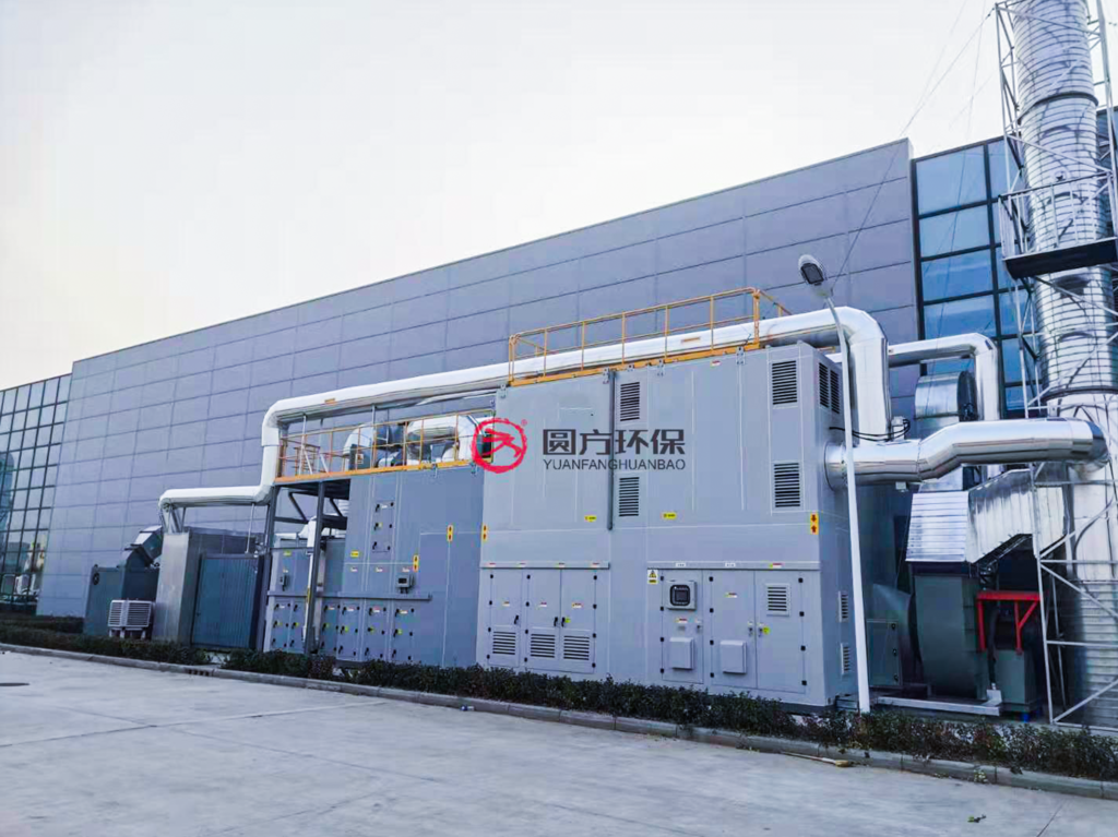
- Understanding Metallurgical Dust-Laden Emissions
- How Biofiltration Treats Dual-Phase Pollution
- The Biofilm Mechanism
- Dust Filtration Role
- System Architecture: Pre-Treatment + Biofiltration
- Stage 1: High-Efficiency Dust Pre-Separation
- Stage 2: Gas Conditioning
- Stage 3: Biofilter Unit(s)
- Key Design Parameters
- Media Selection for Metallurgical Applications
- Case Study: Steel Foundry Cupola Exhaust Treatment
- Operation & Maintenance Best Practices
- Daily Monitoring
- Weekly Tasks
- Quarterly Preventive Maintenance
- Annual Overhaul
- Troubleshooting Common Issues
- Economic Comparison: Biofiltration vs. Wet Scrubbing
- Conclusion
Metallurgical facilities — including steel mills, iron foundries, aluminum smelters, and non-ferrous metal processing plants — generate significant volumes of dust-laden exhaust gas. Unlike pure gaseous emissions, these streams carry both particulate matter (PM) and acidic gas components such as SO₂, HCl, and HF. Treating this dual-phase pollution with conventional wet scrubbers alone often leads to high water consumption, sludge disposal challenges, and secondary pollution risks. Biofiltration has emerged as an increasingly viable alternative, offering simultaneous dust capture and biological degradation of acid gases through a single integrated system. This article provides a comprehensive engineering guide to biofilter selection, design parameters, and operational strategies for metallurgical dust-laden exhaust treatment.
Understanding Metallurgical Dust-Laden Emissions
Metallurgical processes produce exhaust streams with distinct characteristics that directly influence treatment equipment selection:
- Electric Arc Furnace (EAF) off-gas: Contains iron oxide dust (20–50 g/Nm³ raw), CO, NOₓ, and trace heavy metals. Temperature at the furnace outlet can exceed 1,200°C, requiring extensive cooling before any biological treatment stage.
- Blast furnace top gas: Carries fine coke and ore particulates at 5–20 g/Nm³, plus SO₂ from sulfur-bearing raw materials. The dust is abrasive and can mechanically degrade filter media over time.
- Aluminum smelting pot gas: Emits alumina dust mixed with hydrogen fluoride (HF) and perfluorocarbons (PFCs). HF is highly water-soluble, making it amenable to biological absorption, but requires specialized microorganisms tolerant to fluoride toxicity.
- Foundry cupola exhaust: Contains carbonaceous soot, silica dust, and CO. The particle size distribution is typically bimodal, with both submicron and coarse fractions present.
- Sinter plant off-gas: Combines iron ore dust with SO₂, NOₓ, and dioxins at flow rates often exceeding 500,000 Nm³/h.
The defining challenge is that particulate load must be reduced before biological treatment, as excessive dust accumulation on biofilm surfaces blocks gas-liquid mass transfer and suffocates the microbial community.
How Biofiltration Treats Dual-Phase Pollution
The Biofilm Mechanism
A biofilter consists of a packed bed of organic or inert media on which a consortium of microorganisms forms a biofilm. As contaminated air passes through the media, pollutants transfer from the gas phase into the biofilm’s aqueous layer, where microorganisms metabolize them into harmless end products — primarily CO₂, H₂O, and biomass. For acid gases, the conversion pathway is as follows:
- SO₂ → H₂SO₄: Sulfur-oxidizing bacteria (e.g., Thiobacillus spp.) oxidize dissolved SO₂ to sulfate, which can be neutralized by buffering media components.
- H₂S → S⁰ → H₂SO₄: A two-stage oxidation by sulfide-oxidizing bacteria, with elemental sulfur as an intermediate in oxygen-limited zones.
- HF → F⁻: Fluoride accumulates in the liquid phase and requires periodic flushing to prevent toxic buildup for the microbial population.
Dust Filtration Role
While biofilters are primarily designed for gaseous pollutant removal, the packed bed also functions as a depth filter for particulate matter. Fine dust particles are captured through interception, inertial impaction, and diffusion within the porous media structure. However, this dual function introduces a critical design trade-off: media with high specific surface area (SSA) provides excellent biological performance but clogs more rapidly under dust loading. Conversely, coarse media resists clogging but offers less biofilm attachment surface.
System Architecture: Pre-Treatment + Biofiltration
A properly designed metallurgical biofiltration system follows a staged architecture to handle the dust load without compromising biological performance:
Stage 1: High-Efficiency Dust Pre-Separation
Before the biofilter, a pre-treatment stage reduces inlet dust concentration to below 10–30 mg/Nm³. Common configurations include:
- Cyclone + Bag Filter: The cyclone removes coarse particles (>10 μm) via centrifugal force, while the bag filter captures fine particulates down to 0.5 μm. This combination achieves >99% overall dust removal efficiency and protects downstream equipment.
- Wet Electrostatic Precipitator (WESP): For exhaust streams with sticky or hygroscopic dust (e.g., aluminum smelting), WESP offers superior performance without the filter-bag blinding issues common in dry systems.
- Venturi Scrubber: When the exhaust also contains tarry aerosols, a Venturi stage can condense and remove these compounds before they foul the biofilter media.
Stage 2: Gas Conditioning
Between pre-treatment and biofiltration, the gas stream must be conditioned to meet biological requirements:
- Temperature control: Mesophilic biofilters operate optimally at 25–35°C. Metallurgical exhaust typically requires cooling via heat exchangers or quench towers. A temperature exceeding 40°C for extended periods will denature key enzymes and collapse the microbial community.
- Humidification: The gas must reach >95% relative humidity before entering the biofilter. Dry gas desiccates the biofilm within hours. A pre-humidification chamber with water spray nozzles is standard.
- pH buffering: Acid gas absorption generates acidity. Media should incorporate buffering agents such as limestone chips, crushed seashells, or calcium carbonate pellets (typically 5–10% by volume of the media blend).
Stage 3: Biofilter Unit(s)
The biofilter itself can be configured as:
- Open single-bed biofilter: Suitable for flow rates up to 50,000 Nm³/h. Media depth 1.0–1.5 m, footprint ~200–500 m² per 10,000 Nm³/h. Low capital cost but large land requirement.
- Modular enclosed biofilter: Containerized or multi-stage vessels for flow rates of 10,000–100,000 Nm³/h. Smaller footprint, better process control, but higher capital cost.
- Biotrickling filter: An inert packed bed with continuous liquid recirculation. Better suited when acid gas loading is high and regular flushing of accumulated salts is necessary.
Key Design Parameters
| Parameter | Recommended Range | Notes |
|---|---|---|
| Empty Bed Residence Time (EBRT) | 30–60 seconds | Higher dust load → longer EBRT to allow dust capture without channeling |
| Surface Loading Rate | 50–150 m³/m²·h | Lower end for dusty streams; higher end for pre-filtered gas |
| Media Depth | 1.0–1.8 m | Multi-layer design recommended: coarse layer (bottom) → fine bioactive layer (top) |
| Media Porosity | 40–60% | Lower porosity increases pressure drop and clogging risk |
| Moisture Content | 40–60% (w/w) | Maintained by humidification + periodic surface irrigation |
| pH Range | 6.5–7.5 | Buffering media compensates for acid production; leachate pH monitored weekly |
| Pressure Drop | 100–500 Pa (clean) Max 1,500 Pa (before maintenance) | Pressure drop exceeding 1,500 Pa indicates clogging and requires media agitation or partial replacement |
| Inlet Dust Concentration | <30 mg/Nm³ (after pre-treatment) | Higher levels accelerate media replacement cycles; aim for <10 mg/Nm³ for extended media life |
| Organic Load | 10–100 g/m³·h (per pollutant) | Depends on pollutant biodegradability; SO₂ and H₂S are highly biodegradable |
Media Selection for Metallurgical Applications
Biofilter media must simultaneously support microbial growth, resist compaction under dust load, and provide buffering capacity against acid gases. The following media blends have demonstrated strong performance in metallurgical installations:
- Wood chips + compost + limestone (50:40:10): Cost-effective baseline. Wood chips provide structural porosity, compost supplies nutrients and inoculum, and limestone buffers acid production. Typical service life: 2–3 years under moderate dust loading.
- Lava rock + peat + calcium carbonate (60:30:10): Higher mechanical strength, resists compaction better. Suitable for exhaust streams with intermittent high dust spikes. Service life: 3–5 years.
- Polyurethane foam + activated carbon + seashell granules (50:30:20): Synthetic media blend for biotrickling filter configurations. The foam provides high SSA (300–600 m²/m³), activated carbon adsorbs peak loads, and seashell granules buffer pH. Washable and reusable, extending service life beyond 5 years.
- Ceramic Raschig rings + compost extract (inert media + liquid inoculum): For biotrickling filters treating HF-containing exhaust. Ceramic media is chemically inert to fluoride attack and can be periodically flushed to remove accumulated fluoride salts.
Case Study: Steel Foundry Cupola Exhaust Treatment
A medium-sized steel foundry in Jiangsu Province operating two 5-ton cupola furnaces required an exhaust treatment system to comply with China’s GB 9078-1996 emission standards for industrial furnaces. The exhaust stream characteristics were:
- Flow rate: 45,000 Nm³/h (combined from both cupolas)
- Dust concentration (raw): 800–1,500 mg/Nm³
- SO₂: 120–250 mg/Nm³
- Temperature: 180–220°C (after heat recovery)
- Particle size distribution: 60% < 10 μm, 15% < 2.5 μm
System design solution:
- Cyclone pre-separator (2× parallel, Φ2.2 m): Removed 85% of coarse dust, reducing load to ~150 mg/Nm³ downstream.
- Pulse-jet bag filter (PTFE membrane bags, 1,200 m² filtration area): Achieved outlet dust concentration of <8 mg/Nm³.
- Gas conditioning tower: Spray-cooled gas from 200°C to 32°C while raising relative humidity to 98%.
- Two-stage modular biofilter: Each stage 120 m² footprint × 1.5 m media depth, EBRT 38 seconds. Media blend: wood chips (50%) + mature compost (35%) + crushed limestone (15%).
Performance after 12 months of continuous operation:
- SO₂ removal efficiency: 92–97% (outlet < 20 mg/Nm³)
- Outlet dust: < 5 mg/Nm³ (combined system)
- Pressure drop: Stable at 280–350 Pa across biofilter beds
- Media replacement: One partial top-layer replacement at month 10 (15% of bed volume)
- Leachate pH: Maintained at 6.8–7.3 with existing buffer capacity — no external pH adjustment required
The total system achieved full regulatory compliance with operating costs approximately 40% lower than the previously considered wet scrubber + chemical dosing alternative, primarily due to the elimination of continuous NaOH consumption.
Operation & Maintenance Best Practices
Daily Monitoring
- Record pressure drop across each biofilter stage. A 20% increase over baseline within 48 hours indicates abnormal dust breakthrough or media compaction.
- Check humidification system spray nozzles for clogging. Uneven moisture distribution causes dry zones where biofilm dies and gas bypasses untreated.
- Monitor inlet and outlet gas temperature. A sudden rise suggests cooling system malfunction, which can be catastrophic for the biomass.
Weekly Tasks
- Measure leachate pH and conductivity. Declining pH indicates buffer depletion; rising conductivity signals salt accumulation from acid neutralization.
- Inspect media surface for signs of crusting, channeling, or uneven settlement. Rake the top 5–10 cm if crusting is observed.
- Verify pre-treatment dust removal efficiency via isokinetic sampling at the biofilter inlet.
Quarterly Preventive Maintenance
- Collect media samples at three depths (surface, mid-bed, bottom) for moisture content, pH, and microbial activity (ATP assay or respiration test).
- Flush biotrickling filter packing with fresh water to remove accumulated salts. For systems treating HF, flush volume should be 2–3× the liquid hold-up.
- Replace or replenish buffer material (limestone/calcium carbonate) if media pH has dropped below 6.0.
Annual Overhaul
- Replace top 20–30 cm of biofilter media, which accumulates the most dust and experiences the highest acid load.
- Inspect and clean all distribution piping, spray nozzles, and condensate drains.
- Re-inoculate with fresh compost or commercial microbial culture if removal efficiency shows a declining trend not explained by physical or chemical factors.
Troubleshooting Common Issues
- Symptom: Rising pressure drop + declining removal efficiency. Cause: Media compaction from dust overloading or excessive moisture. Solution: Reduce inlet dust load (check pre-filter), rake media surface, consider partial media replacement.
- Symptom: Low pH leachate + good removal efficiency. Cause: Buffer material nearly exhausted; system still performing but approaching failure. Solution: Top-dress with fresh limestone chips (2–3 kg/m² bed area).
- Symptom: Ammonia odor from biofilter. Cause: Anaerobic zones developing from over-wetting or excessive organic nitrogen in media. Solution: Reduce irrigation rate, increase gas flow temporarily to dry bed, or add coarse bulking agent to improve drainage.
- Symptom: Fine dust visible at biofilter outlet. Cause: Channeling — gas bypasses through cracks or preferential flow paths. Solution: Re-distribute and compact media surface, check media support grid for damage.
Economic Comparison: Biofiltration vs. Wet Scrubbing
For a 50,000 Nm³/h metallurgical exhaust stream requiring SO₂ removal to <30 mg/Nm³, the 5-year life-cycle cost comparison is instructive:
- Wet scrubber (packed tower + NaOH dosing): Capital ~$120,000; annual operating cost ~$45,000 (NaOH, water, sludge disposal, electricity); 5-year total ~$345,000.
- Biofiltration system (cyclone + bag filter + biofilter): Capital ~$180,000; annual operating cost ~$18,000 (media replacement, electricity, water); 5-year total ~$270,000.
While the biofiltration system carries a higher initial capital investment, the dramatically lower chemical and waste disposal costs result in a payback period of approximately 2.5 years. For facilities operating continuously, the savings become increasingly compelling over a 10–15 year equipment lifetime.
Conclusion
Biofiltration represents a mature, cost-effective technology for treating dust-laden acid gas emissions from metallurgical operations — provided the system is engineered with adequate pre-treatment, proper media selection, and disciplined O&M protocols. The key to success lies in recognizing that the biofilter is not merely a gas treatment device but a living engineered ecosystem that requires balanced moisture, pH, nutrient, and dust-load management. When these conditions are met, biofiltration systems routinely achieve 90–98% acid gas removal efficiency with operating costs 40–60% below chemical scrubbing alternatives, making them an increasingly attractive choice for metallurgical facilities worldwide.
For inquiries, contact Yfep@yf-ep.com | www.xxyuanfang.cn