
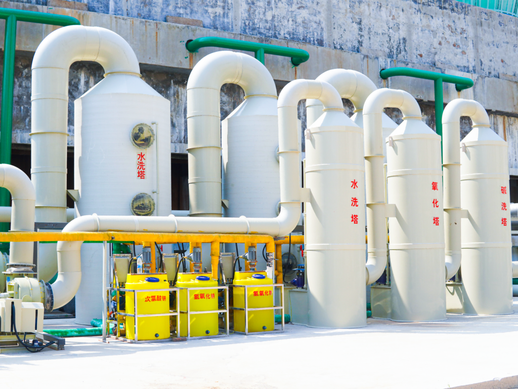
- Introduction: Why Falling Film Absorption Matters in Acid Gas Scrubbing
- 1. Working Principle of the Falling Film Absorption Tower
- 1.1 Core Mechanism
- 1.2 Comparison with Alternative Scrubber Technologies
- 2. Key Design Parameters and Engineering Calculations
- 2.1 Tube-Side Design
- 2.2 Liquid Distribution System
- 2.3 Key Performance Parameters
- 3. Material Selection and Corrosion Protection
- 3.1 The Material Compatibility Matrix
- 3.2 Practical Material Selection Strategy
- 3.3 Corrosion Monitoring and Protection Systems
- 4. Industrial Case Study: HCl Recovery at a Chlorinated Organic Chemical Plant
- 4.1 Background
- 4.2 Solution: Falling Film Absorber Retrofit
- 4.3 Performance Results (12-Month Operating Data)
- 5. Operational Best Practices and Maintenance
- 5.1 Startup and Shutdown Procedures
- 5.2 Common Operating Problems and Solutions
- 5.3 Performance Monitoring KPIs
- 6. Economic Analysis: CAPEX vs. OPEX Considerations
- Conclusion
Introduction: Why Falling Film Absorption Matters in Acid Gas Scrubbing
In chemical manufacturing facilities — from chlor-alkali plants to fine chemical synthesis units — acid-laden exhaust streams pose significant compliance and equipment integrity challenges. Hydrogen chloride (HCl), sulfur dioxide (SO2), nitrogen oxides (NOx), and hydrogen fluoride (HF) are among the most common acidic pollutants requiring abatement before atmospheric discharge.
While spray towers and packed towers dominate much of the acid gas scrubbing landscape, the falling film absorption tower occupies a distinct and often overlooked niche. This equipment type excels in scenarios where high-concentration acid gases must be absorbed with simultaneous heat removal — a combination that conventional scrubbers struggle to handle efficiently.
This article provides a detailed engineering reference for process engineers, EHS managers, and plant operators evaluating falling film absorber technology for chemical acid waste gas treatment. We cover working principles, selection criteria, critical design parameters, material compatibility, corrosion protection strategies, and operational data from industrial deployments.
1. Working Principle of the Falling Film Absorption Tower
1.1 Core Mechanism
A falling film absorber operates on a fundamentally different mass transfer principle compared to spray or packed-bed scrubbers. The key distinction lies in how the liquid phase is distributed and how gas-liquid contact occurs:
- Liquid distribution: The scrubbing liquid (typically water, alkaline solution, or a specialized solvent) is fed at the top of vertical tubes and flows downward as a thin, uniform film along the inner wall of each tube. This is achieved through precision-designed liquid distributors — either weir-type, orifice-type, or slotted-cap designs.
- Gas flow: The acid-laden gas stream can be introduced either co-currently (flowing downward with the liquid film) or counter-currently (flowing upward against the falling liquid). Co-current operation is more common in falling film absorbers because it avoids flooding limitations and allows higher gas velocities.
- Mass transfer: Absorption occurs at the gas-liquid interface across the thin film. Because the film thickness is typically only 0.3–1.0 mm, the liquid-side mass transfer resistance is exceptionally low, enabling rapid absorption of highly soluble gases like HCl and HF.
- Heat transfer: A critical advantage — the shell side of the absorber can be cooled using jacket water or an external cooling circuit. This simultaneous heat removal is essential when absorbing high-concentration acid gases, where the exothermic absorption reaction can raise temperatures significantly and reduce absorption efficiency.
1.2 Comparison with Alternative Scrubber Technologies
Understanding when a falling film absorber outperforms alternatives is essential for proper process selection:
| Parameter | Falling Film Absorber | Packed Tower | Spray Tower |
|---|---|---|---|
| Gas concentration range | High (>5,000 ppm) | Medium (500–5,000 ppm) | Low–Medium (<2,000 ppm) |
| Heat removal capability | Excellent | Poor | Moderate |
| Pressure drop | Low (100–300 Pa) | Medium–High (300–800 Pa) | Low (50–200 Pa) |
| Turndown ratio | 3:1 | 4:1 | 5:1 |
| Fouling tendency | Low (smooth surfaces) | High (packing clogging) | Low |
| Capital cost | Higher | Moderate | Lower |
| Best application | HCl, HF, SO2 recovery; high-temp inlet | General acid scrubbing | Dust + acid gas; large volumes |
2. Key Design Parameters and Engineering Calculations
2.1 Tube-Side Design
The heart of a falling film absorber is its tube bundle. Critical design decisions include:
- Tube diameter: Typically 25–50 mm ID. Smaller diameters provide higher surface area per unit volume but increase the risk of maldistribution. For most chemical acid gas applications, 32–38 mm ID tubes strike the optimal balance.
- Tube length: Generally 3–6 meters. Longer tubes increase residence time and absorption efficiency, but beyond approximately 5 meters, the film may break down due to wave formation and dry-spot development.
- Tube material: The single most consequential specification. See Section 3 for detailed material selection guidance.
- Number of tubes: Determined by required gas flow rate and desired superficial gas velocity (typically 8–15 m/s for co-current operation).
2.2 Liquid Distribution System
Uniform liquid distribution across all tubes is the critical success factor for falling film absorbers. Even a 5% variation in per-tube liquid flow can reduce overall absorption efficiency by 15–20%. Three common distributor designs are used:
Weir-type distributors use overflow weirs to split liquid evenly. They are simple, robust, and clog-resistant but require precise leveling (tolerance within 2 mm/m).
Orifice-type distributors use calibrated holes to meter liquid flow to each tube. They offer excellent distribution accuracy (±3%) but are susceptible to clogging if the scrubbing liquid contains suspended solids.
Slotted-cap distributors combine a cap over each tube with radial slots. This design is self-cleaning to some degree and handles moderate solids loading better than orifice types.
2.3 Key Performance Parameters
Engineers should design around these target parameters for chemical acid gas service:
- Liquid loading rate: 0.5–2.0 m³/h per tube (for 32 mm ID). Below the minimum, film breakup occurs; above the maximum, the film thickens and mass transfer efficiency drops.
- Wetting rate (Γ): 0.3–1.0 kg/(m·s). Calculated as liquid mass flow rate divided by tube perimeter. Values below 0.2 kg/(m·s) risk dry spots.
- Gas velocity: 8–15 m/s (co-current). Counter-current operation is limited to approximately 5–8 m/s to avoid flooding.
- Removal efficiency: >99% for HCl; >95% for HF; >90% for SO₂ with alkaline scrubbing solution.
- Heat transfer coefficient: 500–1,500 W/(m²·K) on the tube side, enabling 70–85% heat removal through the shell-side cooling medium.
3. Material Selection and Corrosion Protection
3.1 The Material Compatibility Matrix
Acid gas service demands meticulous material selection. The table below summarizes material suitability for common acid gas constituents:
| Material | HCl | HF | SO2 | NOx | H2SO4 Mist | Relative Cost |
|---|---|---|---|---|---|---|
| 304 SS | ❌ Poor | ❌ Poor | ⚠ Fair | ✓ Good | ❌ Poor | 1.0× |
| 316L SS | ⚠ Fair | ❌ Poor | ✓ Good | ✓ Good | ⚠ Fair | 1.5× |
| Graphite (impervious) | ✓ Excellent | ✓ Excellent | ✓ Excellent | ✓ Good | ✓ Excellent | 3.0× |
| PTFE-lined CS | ✓ Excellent | ✓ Excellent | ✓ Excellent | ✓ Excellent | ✓ Excellent | 2.5× |
| Hastelloy C-276 | ✓ Excellent | ⚠ Good | ✓ Excellent | ✓ Excellent | ✓ Excellent | 8.0× |
| FRP (Vinyl Ester) | ✓ Excellent | ❌ Poor | ✓ Good | ⚠ Fair | ✓ Good | 0.8× |
3.2 Practical Material Selection Strategy
For typical chemical plant acid gas applications, the following decision framework has proven effective in practice:
HCl absorption (>1,000 ppm): Graphite tubes are the gold standard. While the initial cost is 3× that of 316L stainless steel, graphite offers essentially unlimited service life in HCl service — a compelling lifecycle case. For lower HCl concentrations (<500 ppm) with alkaline scrubbing, FRP (vinyl ester resin) with a corrosion barrier layer is a cost-effective alternative.
Mixed acid streams (HCl + SO₂ + trace HF): PTFE-lined carbon steel tubes with graphite ferrules at the tube sheets provide universal chemical resistance. The liner thickness should be a minimum of 2.5 mm, with spark-testing (15 kV) performed on 100% of tubes before installation.
HF service: This is the most challenging case. HF attacks silica-based materials (glass, ceramics) and most metals. Impervious graphite or PTFE-lined construction is mandatory. Hastelloy C-276 can be used for short-term service but requires careful temperature monitoring — corrosion rates accelerate significantly above 50°C in concentrated HF environments.
3.3 Corrosion Monitoring and Protection Systems
Beyond material selection, an active corrosion management program should include:
- Corrosion coupon racks: Install at the absorber inlet and outlet. Coupons of the same material as the tubes should be weighed monthly to track corrosion rates (target: <0.1 mm/year).
- LPR (Linear Polarization Resistance) probes: For real-time corrosion rate monitoring in the liquid phase. Set alarms at 0.25 mm/year for early warning.
- pH control: Maintain scrubbing liquid pH between 7.5 and 9.0 for alkaline scrubbing. Install redundant pH probes with automatic caustic dosing.
- Cathodic protection: For metallic tube bundles (e.g., 316L), impressed current cathodic protection (ICCP) can significantly extend service life, particularly in chloride-containing environments.
- Regular endoscope inspection: Every 6 months, inspect a representative sample of tubes for pitting, crevice corrosion, or scale formation using a borescope.
4. Industrial Case Study: HCl Recovery at a Chlorinated Organic Chemical Plant
4.1 Background
A medium-scale chlorinated organic chemical facility in eastern China was generating approximately 8,000 Nm³/h of exhaust gas containing 3,500–5,000 ppm HCl from a chlorination reactor vent. The existing packed tower scrubber achieved only 92% removal efficiency, resulting in stack emissions of 280–400 ppm HCl — significantly above the local regulatory limit of 30 ppm.
Two additional problems complicated the retrofit: the exothermic absorption of HCl at this concentration raised the scrubbing liquid temperature to 68°C within 30 minutes of operation, and the packed bed experienced severe fouling from chlorinated organic carryover, requiring monthly cleaning shutdowns.
4.2 Solution: Falling Film Absorber Retrofit
The engineering team designed a two-stage system:
Stage 1 — Falling Film Absorber: A graphite-tube falling film absorber with 180 tubes (38 mm ID × 4.5 m length), co-current gas-liquid flow. Shell-side cooling water at 25°C maintained tube-wall temperatures below 40°C. The absorber produced 18–20% hydrochloric acid as a saleable byproduct, offsetting approximately 60% of the system’s operating cost.
Stage 2 — Packed Tower Polisher: A small downstream packed tower (1.2 m diameter × 3 m bed height) with 2% NaOH scrubbing solution captured residual HCl to achieve final emissions below 10 ppm.
4.3 Performance Results (12-Month Operating Data)
| Parameter | Before Retrofit | After Retrofit | Improvement |
|---|---|---|---|
| HCl removal efficiency | 92% | 99.8% | +7.8% |
| Stack HCl emission | 280–400 ppm | 3–8 ppm | ↓98% |
| Shutdown frequency | Monthly (fouling) | Annual (scheduled PM) | −92% |
| Byproduct HCl quality | N/A (waste) | 18–20% concentration | Revenue stream |
| Annual O&M cost | $48,000 | $31,000 (net, after byproduct credit) | −35% |
5. Operational Best Practices and Maintenance
5.1 Startup and Shutdown Procedures
Falling film absorbers require disciplined operating procedures to prevent damage:
- Startup sequence: Always start the scrubbing liquid circulation first and establish stable film flow on all tubes before introducing the gas stream. Operating even briefly without liquid flow can cause immediate tube damage from concentrated acid condensation.
- Shutdown sequence: Stop gas flow first, then continue liquid circulation for 15–20 minutes to flush residual acid from all surfaces. Follow with a fresh water rinse cycle of 5–10 minutes.
- Emergency shutdown: If liquid circulation fails, an automatic gas isolation damper must close within 5 seconds. Provide a UPS-backed controller for this interlock.
5.2 Common Operating Problems and Solutions
Film breakdown / dry spots: The most common failure mode, typically caused by insufficient liquid loading or distributor clogging. Symptoms include localized hot spots on the tube exterior and reduced absorption efficiency. Solution: Increase liquid circulation rate by 20% above minimum; clean or replace distributor elements.
Tube-side scaling: Calcium or magnesium salt precipitation from hard water-based scrubbing solutions. Scale layers as thin as 0.5 mm can reduce heat transfer by 40%. Solution: Use softened water for makeup; implement periodic acid cleaning (5% HCl at 40°C for 2 hours, followed by thorough neutralization).
Shell-side fouling: If using untreated cooling water on the shell side, biofouling and scale can accumulate. Maintain cooling water treatment with biocide and scale inhibitor dosing. Design shell-side access for mechanical cleaning every 12–18 months.
5.3 Performance Monitoring KPIs
Establish a dashboard tracking these key indicators:
- ΔP across absorber: Baseline 100–150 Pa. Any increase >50% indicates developing blockage or scaling.
- Gas outlet temperature: Should be within 5°C of scrubbing liquid inlet temperature. Larger ΔT suggests reduced heat transfer efficiency.
- Scrubbing liquid pH: Continuous monitoring with daily grab-sample verification.
- Makeup water consumption: Sudden increases may indicate tube leaks or distributor damage.
- Byproduct acid concentration: If recovering acid, daily titration to confirm concentration trending.
6. Economic Analysis: CAPEX vs. OPEX Considerations
Falling film absorbers carry a higher initial investment compared to spray towers or simple packed towers — typically 1.5× to 2.5× the capital cost for equivalent gas flow capacity. However, the total cost of ownership (TCO) analysis often favors falling film technology in the right applications:
- Energy savings: Lower pressure drop (100–300 Pa vs. 300–800 Pa for packed towers) translates to 40–60% lower fan power consumption over the equipment lifetime.
- Reduced chemical consumption: The counter-current or co-current film contact achieves higher mass transfer efficiency, reducing caustic consumption by 15–25% compared to spray towers for equivalent removal.
- Maintenance labor: Smooth tube surfaces resist fouling, reducing cleaning frequency. Annual maintenance hours are typically 60–80 for a falling film unit vs. 150–200 for a packed tower of similar capacity.
- Byproduct recovery potential: Where acid recovery is feasible (especially HCl), the revenue stream can fully offset operating costs within 18–36 months.
- Service life: Graphite-tube falling film absorbers in HCl service routinely achieve 15–20 year service lives with proper maintenance, compared to 5–8 years for metallic packed towers in similar service.
Conclusion
The falling film absorption tower represents a specialized but highly effective solution for chemical acid waste gas treatment, particularly where high-concentration acid gases (HCl, HF, SO₂) must be handled with simultaneous heat removal and potential byproduct recovery.
Key takeaways for engineering teams evaluating this technology:
- Application sweet spot: Gas streams with >3,000 ppm acid gas, where exothermic absorption heat would otherwise degrade performance in conventional scrubbers.
- Critical design element: The liquid distribution system is the single most important component — invest in precision manufacturing and rigorous commissioning verification.
- Material strategy: Graphite tubes for HCl service; PTFE-lined for mixed acids with HF; FRP as a cost-effective option for moderate-duty applications.
- Lifecycle economics: While CAPEX is 1.5–2.5× higher, the TCO advantage over 10 years typically ranges from 25–40% in appropriate applications, driven by lower energy costs, reduced maintenance, and potential byproduct revenue.
As environmental regulations continue to tighten globally — with HCl emission limits dropping from 50–100 ppm to 10–30 ppm in many jurisdictions — falling film absorption technology deserves a prominent place in every chemical engineer’s emission control toolkit.
For inquiries, contact Yfep@yf-ep.com | www.xxyuanfang.cn