
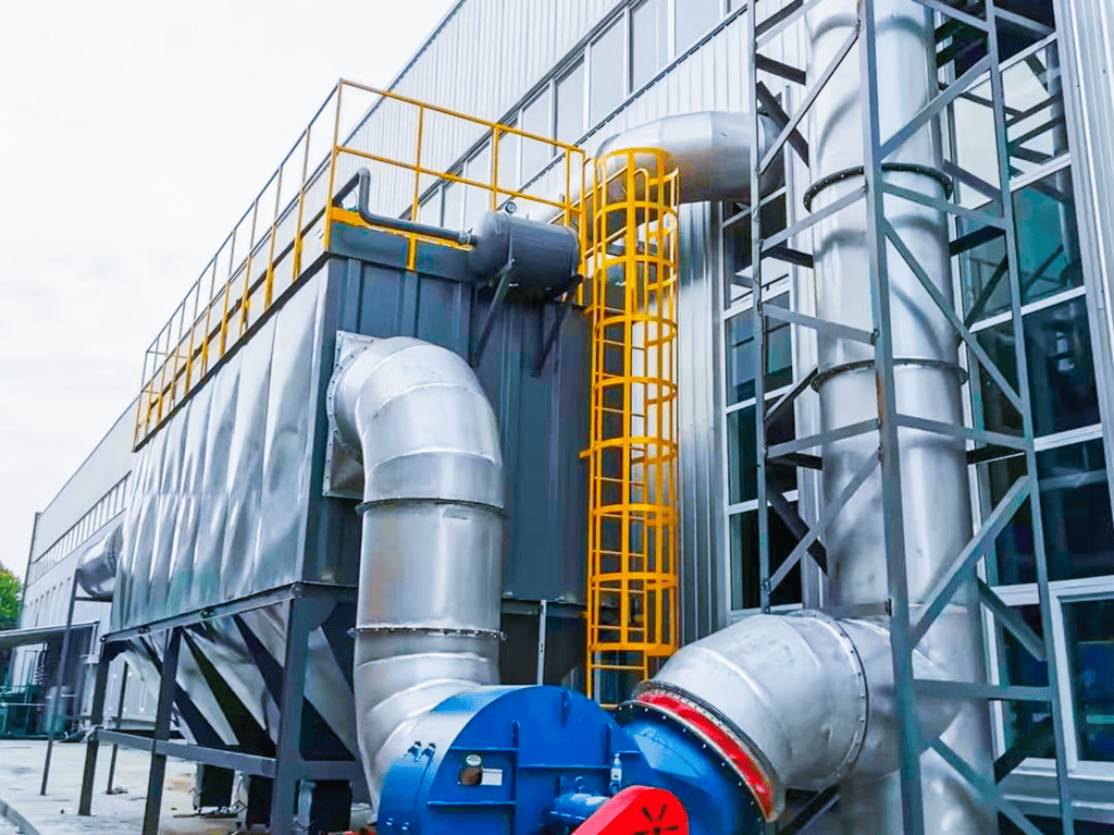
Chlorine gas is one of the most widely used industrial chemicals — essential for water treatment, PVC production, pharmaceutical synthesis, and pulp bleaching. But it is also one of the most hazardous. A single uncontrolled release can cause fatalities, plant evacuations, and catastrophic environmental damage. This is where an emergency chlorine gas scrubber becomes the last line of defense: they are the last line of defense between a process upset and a major incident.
In this article, we break down the engineering fundamentals behind a chlorine gas scrubber — a specialized wet scrubber — for emergency response — from reaction chemistry and system architecture to sizing calculations and compliance requirements. If you design, operate, or audit chemical safety systems, this guide is for you.
Why a Chlorine Gas Scrubber Is Non-Negotiable for Emergency Response
Chlorine (Cl₂) is a greenish-yellow gas with a pungent, suffocating odor. It is approximately 2.5 times heavier than air, which means released chlorine tends to accumulate in low-lying areas, drainage pits, and basements — exactly where personnel are likely to be present. The Immediately Dangerous to Life or Health (IDLH) concentration for chlorine is just 10 ppm, and the OSHA permissible exposure limit (PEL) is a ceiling of 1 ppm.
In industrial settings, chlorine is typically stored as a liquefied gas under pressure. When a storage tank, cylinder manifold, or process pipeline fails — due to corrosion, mechanical damage, or overpressure — the rapid phase change from liquid to gas can release enormous volumes in seconds. An emergency scrubbing system must be capable of handling this worst-case release scenario and neutralizing the chlorine before it escapes to atmosphere.
Regulatory frameworks including OSHA 1910.119 (Process Safety Management), EPA Risk Management Program (RMP), and the European Seveso III Directive all require facilities handling chlorine above threshold quantities to have engineered mitigation systems in place. Emergency scrubbers are the most widely adopted solution.
Absorption Chemistry: How NaOH Neutralizes Chlorine
The core chemistry of a chlorine emergency scrubber relies on caustic scrubbing using sodium hydroxide (NaOH) solution. Two competing reactions occur depending on operating conditions:
Primary reaction (low temperature, excess NaOH):
Cl₂ + 2NaOH → NaCl + NaOCl + H₂O
This produces sodium chloride (table salt) and sodium hypochlorite (bleach). The reaction is exothermic but manageable under controlled conditions. The resulting sodium hypochlorite solution can be reused or neutralized before disposal.
Secondary reaction (elevated temperature):
3Cl₂ + 6NaOH → 5NaCl + NaClO₃ + 3H₂O
At temperatures above approximately 45°C, sodium chlorate (NaClO₃) formation becomes significant. This is undesirable because chlorate is a strong oxidizer and presents its own handling hazards. Effective temperature control in the recirculation loop is therefore critical.
The scrubbing liquor is typically maintained at 10–20 wt% NaOH with a target pH above 12. As chlorine is absorbed, the pH drops. Once the pH falls below approximately 9, the absorption efficiency declines sharply. This is why emergency scrubbers include online pH monitoring and automatic caustic dosing systems — the system must remain ready for operation at any moment, even after months of standby.
System Architecture: Components of a Chlorine Emergency Scrubber
A properly designed emergency chlorine absorption system consists of several integrated subsystems:
1. Absorption Tower (Packed Bed or Spray Tower)
The heart of the system. Most emergency scrubbers use a counter-current packed bed column filled with high-surface-area random packing (Pall rings, Raschig rings, or structured packing). Chlorine-laden air enters at the bottom and flows upward; NaOH solution is sprayed from the top and flows downward. The large gas-liquid interfacial area in the packing maximizes mass transfer.
Alternatively, spray towers with multiple spray levels can be used, particularly for very large gas flow rates. Spray towers have lower pressure drop but require higher liquid circulation rates to achieve equivalent removal efficiency.
Materials of construction must be carefully selected: the tower shell is typically FRP (fiberglass-reinforced plastic) or PVC/CPVC-lined steel to resist both the alkaline scrubbing liquor and the corrosive wet chlorine environment. Internal packing supports, distributors, and mist eliminators are often PP or PVDF.
2. Recirculation Tank and Pump System
A tank at the base of the tower holds the scrubbing liquor. During an emergency event, the recirculation pump drives NaOH solution from the tank to the top of the tower. The pump must be rated for corrosive service and sized to deliver the design liquid-to-gas (L/G) ratio — typically 3–8 L/m³ for packed bed chlorine scrubbers, depending on inlet concentration and required removal efficiency.
Dual (duty/standby) pump configuration with automatic switchover is standard practice for safety-critical applications.
3. Exhaust Fan and Ductwork
The exhaust fan draws air from the chlorine storage or process area through ductwork into the scrubber and discharges treated air through a stack. The fan is typically located on the clean side (after the scrubber) to minimize corrosion exposure. Ductwork from chlorine storage areas must be fabricated from corrosion-resistant materials and sloped to prevent liquid pooling.
4. Chemical Dosing and pH Control
An automated NaOH dosing system maintains the scrubbing liquor at the target concentration. Online pH and conductivity sensors in the recirculation loop provide continuous monitoring. When pH drops below the setpoint, a metering pump injects fresh 50% NaOH into the tank. This system must function reliably even after long standby periods — sensor fouling and crystallization in dosing lines are common failure modes that require regular preventive maintenance.
5. Instrumentation and Safety Interlocks
Emergency scrubbers are integrated with the plant’s overall safety instrumented system (SIS). Chlorine gas detectors in the storage area trigger automatic scrubber startup when concentrations exceed a preset threshold (typically 0.5–1 ppm). Key interlocks include:
- Low circulation flow → alarm and backup pump start
- Low pH in recirculation → automatic caustic dosing
- High liquid temperature → cooling water valve activation
- Fan failure → automatic damper closure on chlorine source
- High discharge Cl₂ concentration → plant evacuation alarm
Key Design Parameters and Sizing Methodology
Proper sizing of an emergency chlorine scrubber requires defining the design basis accident scenario. The key inputs are:
Worst-case release rate (kg/h Cl₂): This is determined through hazard analysis — typically the complete loss of containment from the largest single chlorine container (ton container, cylinder, or storage tank) over a defined release duration. For a 1-ton chlorine container, the peak release rate can exceed 500 kg/h under adiabatic flash conditions.
Ventilation air flow rate (m³/h): The scrubber must process the ventilation air from the chlorine storage enclosure. Building volume and air change rate (typically 6–12 air changes per hour for occupied areas, higher for storage) define the minimum flow. A typical chlorine cylinder storage room of 200 m³ with 10 ACH requires 2,000 m³/h scrubber capacity.
Required removal efficiency: The target outlet concentration is typically ≤ 5 mg/Nm³ (approximately 1.7 ppm), aligned with most national emission standards. For a worst-case inlet of 250,000 mg/Nm³ (25 vol%), this demands 99.998% removal efficiency.
Tower diameter calculation: Based on the design gas flow rate and the allowable superficial gas velocity (typically 0.5–1.5 m/s for packed columns, limited by flooding correlation):
D = √(4Q / πv)
where Q = gas volumetric flow (m³/s), v = superficial velocity (m/s)
Packing height determination: Using the number of transfer units (NTU) method based on the required removal efficiency and the height of a transfer unit (HTU) for chlorine-NaOH absorption (typically 0.3–0.6 m for modern random packing):
H = NTU × HTU
where NTU = ln(C_in / C_out) for dilute systems
For the 99.998% removal example above: NTU = ln(250,000/5) ≈ 10.8, requiring approximately 4–6 meters of packed bed height with typical HTU values.
NaOH consumption: Stoichiometrically, 1 kg of Cl₂ requires approximately 1.13 kg of NaOH (100% basis). In practice, a 20–50% excess is maintained to account for CO₂ absorption from air and to ensure complete reaction kinetics. For a 1-ton chlorine release, plan for approximately 1,500–1,700 kg of NaOH (100% basis), equivalent to 3,000–3,400 liters of 50% caustic solution.
Case Study: Chlor-Alkali Plant Emergency Scrubber Retrofit
A chlor-alkali facility in Southeast Asia producing 150,000 tonnes/year of caustic soda was storing up to 60 tonnes of liquefied chlorine in four 15-tonne horizontal storage tanks. The existing emergency scrubber — a simple spray tower installed in 1998 — was failing to meet updated emission standards and showed significant FRP delamination near the chlorine inlet nozzle.
Challenge: The facility needed to upgrade to a system capable of handling the worst-case release from a single 15-tonne tank (estimated peak release rate of 3,200 kg/h Cl₂) while maintaining normal plant operations during the retrofit.
Solution: A two-stage counter-current packed bed system was installed:
- Stage 1 (quench): High-liquid-rate spray section for initial chlorine absorption and gas cooling, with a dedicated recirculation loop and heat exchanger to manage the exotherm
- Stage 2 (polishing): 5.5 m packed bed with structured packing (specific surface area 250 m²/m³), fed with fresh 15% NaOH from a separate recirculation system
- Tower diameter: 2.4 m (design flow 28,000 m³/h, superficial velocity 1.7 m/s)
- Fan: 45 kW centrifugal, FRP construction, VFD-controlled for soft start
Results: Commissioning tests demonstrated outlet chlorine concentrations below 1 mg/Nm³ (0.3 ppm) under simulated full-release conditions. The system achieved its design removal efficiency of 99.999%. Regular quarterly functional testing confirmed sustained performance over two years of operation. Total project cost was approximately USD 480,000 with a 14-week installation timeline.
Operation, Maintenance, and Compliance Best Practices
An emergency scrubber that sits idle for 364 days a year must work perfectly on the one day it is needed. This demands a rigorous O&M program:
Monthly checks:
- Verify NaOH tank level and concentration (titration recommended over online sensors alone)
- Inspect recirculation pump seals and bearings; manually jog the standby pump
- Check fan belt tension and vibration readings
- Test chlorine gas detectors with calibration gas
- Cycle emergency dampers to confirm free movement
Quarterly functional testing:
- Run the full system with water (or dilute NaOH) for at least 30 minutes
- Verify all interlocks: low flow, low pH, high temperature, fan failure
- Inspect packing for fouling or channeling — remove manway covers and visually assess the top of the bed
- Calibrate pH and conductivity probes; clean or replace if response time exceeds 30 seconds
Annual activities:
- Full internal inspection of the tower, tank, and ductwork
- Thickness testing of FRP laminates, especially at nozzle connections
- Replace NaOH inventory to prevent carbonate buildup from atmospheric CO₂ absorption
- Review and update the emergency response plan based on any plant modifications
- Conduct a full-scale drill with operations personnel
Compliance documentation: Maintain a scrubber logbook recording all inspections, test results, maintenance activities, and chemical consumption. This documentation is essential for OSHA PSM compliance audits and EPA RMP inspections. Many facilities also integrate scrubber status data into their plant DCS for real-time visibility.
Common Pitfalls and How to Avoid Them
Based on decades of field experience across hundreds of installations, here are the most frequent issues encountered with emergency chlorine scrubbers — and how to prevent them:
- Undersized for the worst case: Always model the release from the largest single container, not the average inventory. A scrubber sized for a 1-ton cylinder will not handle a ruptured 15-ton tank.
- Inadequate materials of construction: Wet chlorine is extremely aggressive. FRP resin selection (vinyl ester vs. polyester) matters enormously. Specify a corrosion barrier with a minimum 2.5 mm resin-rich layer.
- Caustic stratification: In tall tanks without agitation, NaOH concentration can stratify, with weaker solution at the top. Provide tank recirculation or air sparging for homogeneity.
- Sensor drift during standby: pH probes left in stagnant caustic solution for months will drift. Specify sensors designed for continuous high-pH service and implement an automatic retraction/cleaning system.
- Insufficient stack height: Even a properly functioning scrubber discharges air with residual moisture and trace chemicals. Dispersion modeling should confirm that stack emissions do not impact nearby air intakes or populated areas under worst-case meteorological conditions.
Conclusion
An emergency chlorine gas scrubbing system is not a compliance checkbox — it is a fundamental safety asset that protects workers, surrounding communities, and the environment from one of the most hazardous chemicals in industrial use. Getting the design right requires careful hazard analysis, sound chemical engineering, and robust materials selection.
Equally important is the commitment to ongoing maintenance and testing. A scrubber that fails to start during an actual chlorine release is far worse than no scrubber at all — because it creates a false sense of security. The best systems in the world are those that are verified, tested, and maintained as if lives depend on them. Because they do.
For facilities handling chlorine — whether in chlor-alkali production, water treatment, or chemical manufacturing — investing in a properly designed and maintained emergency scrubbing system is not optional. It is the standard of care that responsible operators owe to their people and their communities.
For inquiries, contact Yfep@yf-ep.com | www.xxyuanfang.cn