
- Why RTO Tail Gas Needs Pretreatment
- Spray Tower vs. Packed Tower for RTO Pretreatment
- Spray Tower (Open Spray Scrubber)
- Packed Tower (Packed Bed Scrubber)
- Case Study: Chemical Plant RTO Pretreatment — Xuchang, Henan
- Pretreatment System Design
- Performance Results
- Key Engineering Considerations for RTO Pretreatment Scrubbers
- Material Selection
- pH Control and Chemical Dosing
- Water Balance and Blowdown Management
- O&M Best Practices
- Economic Perspective
- Conclusion
Regenerative Thermal Oxidizers (RTOs) are widely deployed across the chemical manufacturing sector for high-efficiency volatile organic compound (VOC) destruction. However, an often-overlooked aspect of RTO system design is the tail gas pretreatment stage — particularly when the upstream process stream carries significant acid gas loads, particulate matter, or corrosive constituents that can degrade RTO performance, shorten ceramic media life, and trigger emissions non-compliance. This article presents an engineering deep dive into RTO exhaust pretreatment, focusing on spray tower and packed tower scrubber configurations with a real-world case study from a chemical plant in Xuchang, Henan Province.
Why RTO Tail Gas Needs Pretreatment
In chemical production environments, exhaust streams feeding into an RTO are rarely “clean.” Common contaminants that necessitate pretreatment include:
- Acid gases (HCl, HF, SO₂, NOₓ): These corrode RTO internals, attack the ceramic heat exchange media, and produce secondary pollutants if oxidized incompletely.
- Alkaline mists and particulates: Sodium hydroxide or ammonia carryover can foul the ceramic bed, increase pressure drop, and reduce thermal efficiency.
- High-humidity or saturated streams: Excess moisture increases the RTO’s auxiliary fuel consumption and can cause condensation-related corrosion in ductwork.
- Sticky or polymerizing compounds: Certain organic species can polymerize on hot ceramic surfaces, leading to irreversible fouling and costly media replacement.
Without adequate pretreatment, plant operators typically observe a cascade of operational issues: rising pressure drop across the RTO bed, increased natural gas consumption for maintaining oxidation temperature, shortened ceramic media service life (from a design expectation of 8–10 years down to 2–3 years), and eventual regulatory exceedances. A properly designed pretreatment scrubber system — typically a spray tower or packed tower — mitigates all of these risks before the gas stream enters the oxidizer.
Spray Tower vs. Packed Tower for RTO Pretreatment
Selecting the right scrubbing technology depends on the contaminant profile and required removal efficiency. Below is a comparative analysis of the two dominant configurations.
Spray Tower (Open Spray Scrubber)
A spray tower uses high-pressure nozzles to atomize the scrubbing liquid into fine droplets that contact the ascending gas stream in a counter-current or co-current arrangement. The scrubbing mechanism is primarily absorption with inertial impaction for particulates.
Key design parameters:
- Superficial gas velocity: 0.6–1.5 m/s (2–5 ft/s) — lower than packed towers to minimize droplet entrainment
- Liquid-to-gas ratio (L/G): 2–5 L/m³ for acid gas absorption; up to 10 L/m³ for heavy particulate loading
- Residence time: 3–8 seconds for adequate mass transfer
- Nozzle type: Full-cone spiral or tangential-whirl nozzles with droplet Sauter mean diameter (SMD) of 500–1000 μm
- Pressure drop: Typically 150–400 Pa, making it an energy-efficient choice
Advantages for RTO pretreatment: Excellent tolerance for particulate-laden streams without risk of packing fouling; low maintenance; capable of handling high inlet temperatures (up to 80–90°C with appropriate materials); simple internals resistant to plugging.
Limitations: Lower mass transfer efficiency compared to packed towers for highly soluble gases; requires taller vessels to achieve >90% removal of moderately soluble species.
Packed Tower (Packed Bed Scrubber)
A packed tower employs structured or random packing media to maximize gas–liquid interfacial area. The scrubbing liquid is distributed over the packing top and flows downward as a thin film, while the gas moves counter-currently upward.
Key design parameters:
- Superficial gas velocity: 0.8–2.5 m/s (2.6–8 ft/s), limited by flooding point (typically designed at 60–75% of flood velocity)
- Liquid-to-gas ratio (L/G): 1.5–4 L/m³ for most acid gas scrubbing applications
- Packing type: Random packing (Pall rings, Raschig rings, Tri-Packs) or structured packing (corrugated sheets) in PP, PVDF, or FRP depending on corrosion resistance needs
- Packed bed depth: 1.5–3.0 m per stage; multiple stages for >99% removal
- Pressure drop: 200–800 Pa depending on packing type and gas load
Advantages for RTO pretreatment: Significantly higher mass transfer efficiency — capable of 95–99%+ removal for HCl, HF, and SO₂; compact footprint for a given removal duty; well-suited for multi-pollutant scrubbing with staged pH control.
Limitations: Susceptible to fouling from particulates and scaling from hardness ions in the scrubbing solution; higher capital cost than spray towers; requires regular packing inspection and occasional media replacement.
Case Study: Chemical Plant RTO Pretreatment — Xuchang, Henan
A specialty chemical manufacturer in Xuchang operates a three-canister RTO system treating approximately 25,000 Nm³/h of process exhaust from multiple reactor vents and tank breathing lines. The exhaust stream characteristics before pretreatment were as follows:
| Parameter | Value |
|---|---|
| Flow rate | 25,000 Nm³/h |
| HCl concentration | 80–150 mg/Nm³ (peak 300 mg/Nm³) |
| Particulate (PM₁₀) | 30–60 mg/Nm³ |
| Temperature | 45–65°C |
| Relative humidity | 60–80% |
| VOC (as total carbon) | 800–1,500 mg/Nm³ |
The client’s primary concern was accelerated corrosion of the RTO’s ceramic saddles, which had required partial media replacement after only 18 months of operation. Post-mortem analysis confirmed HCl acid attack as the root cause. Additionally, particulate buildup on the cold-face media was increasing pressure drop and forcing more frequent burner cycling.
Pretreatment System Design
After engineering evaluation, a two-stage pretreatment system was specified:
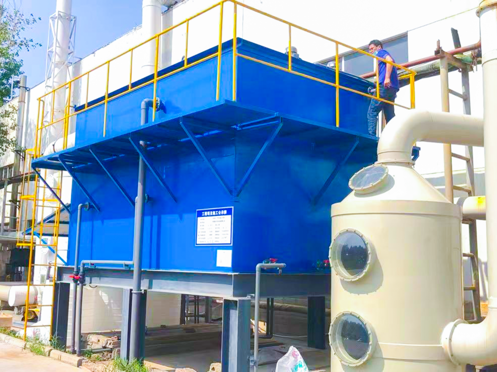
- Stage 1 — Spray Tower (quench + bulk removal): A FRP spray tower, 2.8 m diameter × 6.5 m cylindrical height, equipped with three levels of full-cone spiral nozzles. Scrubbing medium: 5% NaOH solution with pH-controlled dosing. Designed gas velocity: 1.1 m/s. This stage handles both temperature quenching (bringing gas from 65°C to ~35°C) and removes ~85% of HCl and the majority of particulates via inertial impaction.
- Stage 2 — Packed Tower (polishing): A PP packed tower, 2.4 m diameter × 5.0 m packed height, filled with 50 mm PP Pall rings (two beds of 2.5 m each with intermediate liquid redistribution). Scrubbing medium: 3% NaOH, pH maintained at 8.5–9.5. Designed gas velocity: 1.6 m/s. This stage achieves >99% overall HCl removal and handles trace SO₂ and residual acid mists.
- Mist eliminator: Chevron-type at the packed tower outlet, reducing liquid carryover to <10 mg/Nm³ before the gas enters RTO ductwork.
- Recirculation system: Each stage has independent sump tanks (FRP) with level control, pH monitoring, and automated blowdown for dissolved solids management. NaOH dosing pumps are PID-controlled with inline pH probes.
Performance Results
After 12 months of continuous operation, the system demonstrated the following:
- HCl at RTO inlet: Consistently <3 mg/Nm³ (98%+ removal efficiency)
- Particulate at RTO inlet: <5 mg/Nm³ (90%+ removal)
- RTO ceramic media condition: Visual inspection after 12 months showed no visible acid attack or fouling — a dramatic improvement from the pre-treatment baseline
- Pressure drop across RTO: Stabilized at design specification (±5% variation over the year)
- Auxiliary fuel consumption: Reduced by approximately 18% due to lower moisture loading and cleaner media
- NaOH consumption: Averaging 12 kg/h during normal operation, with peak demand of 22 kg/h during high-HCl events
Key Engineering Considerations for RTO Pretreatment Scrubbers
Material Selection
Corrosion resistance is paramount. For HCl and mixed acid service:
- FRP (Fiber-Reinforced Plastic): Preferred for vessel shells, ductwork, and sump tanks. Vinyl ester resin provides excellent resistance to HCl, H₂SO₄, and HF at temperatures up to 90°C. Ensure the corrosion barrier (inner liner) is at least 2.5 mm thick with a resin-rich (90%+) surface veil.
- PP (Polypropylene): Cost-effective for packing media and internal supports at operating temperatures below 80°C. Not recommended for streams containing strong oxidizing agents or aromatic hydrocarbons that can cause swelling.
- PVDF (Polyvinylidene Fluoride): Superior chemical resistance for aggressive mixed-acid environments, albeit at significantly higher cost. Used selectively for critical internals such as nozzles and demister elements.
- Stainless steel 316L / duplex: Generally avoided for HCl service due to chloride stress corrosion cracking risk; acceptable only for non-wetted structural supports external to the gas path.
pH Control and Chemical Dosing
Maintaining the correct pH in each scrubbing stage is critical for both removal efficiency and operational cost:
- Stage 1 (quench/acidic): Target pH 3–5. At this range, HCl absorption is rapid while NaOH consumption is minimized — the bulk acid is neutralized but complete neutralization is deferred to Stage 2.
- Stage 2 (polishing/alkaline): Target pH 8.5–9.5. The slightly alkaline environment ensures complete acid gas removal and provides buffering capacity against concentration spikes.
- Automation: Inline pH probes with PID-controlled metering pumps are strongly recommended. Manual pH control leads to either excessive chemical consumption (over-dosing) or breakthrough events (under-dosing).
Water Balance and Blowdown Management
The scrubbing process generates a continuous liquid blowdown stream containing dissolved salts (NaCl, Na₂SO₄, NaF). Key considerations:
- Blowdown rate is calculated based on the allowable total dissolved solids (TDS) concentration in the recirculating loop — typically 50,000–100,000 mg/L for FRP/PP systems
- Blowdown water must be routed to the plant’s wastewater treatment system; in some jurisdictions, chloride limits in effluent may require evaporation or separate treatment
- Makeup water demand equals evaporation loss (gas humidification) plus blowdown — approximately 1.5–3% of the recirculation flow rate
O&M Best Practices
- Weekly nozzle inspection: Check for clogging or wear patterns. Even a 10% nozzle blockage can reduce removal efficiency by 20–30% due to poor liquid distribution.
- Monthly pH probe calibration: Drifting pH readings are the most common cause of chemical over-consumption and should be addressed through a formal calibration schedule.
- Quarterly packing inspection: During scheduled shutdowns, inspect the top layer of packing for fouling, channeling, or mechanical degradation. Look for “dry spots” that indicate liquid distributor issues.
- Semi-annual sump cleaning: Accumulated sludge and scale in sump tanks reduce effective volume and can clog pump suction strainers.
- Annual RTO media inspection: Even with pretreatment, inspect a sample of ceramic media from the cold face for acid attack indicators (surface pitting, discoloration, weight loss). This provides direct feedback on pretreatment effectiveness.
- Spare parts inventory: Maintain critical spares including spray nozzles (2 full sets), pH probes, recirculation pump mechanical seals, and a representative quantity of packing media for emergency top-up.
Economic Perspective
While adding a pretreatment scrubber system represents a capital investment (typically 15–25% of the RTO system cost), the operational savings are compelling:
- Extended RTO media life: From 2–3 years without pretreatment to 8–10+ years with pretreatment — a 3–5× improvement
- Reduced fuel consumption: 15–20% reduction in natural gas usage
- Avoided compliance penalties: Eliminates the risk of HCl or particulate emission exceedances that can trigger fines and enforcement actions
- Reduced unplanned downtime: Fewer emergency shutdowns for media replacement or RTO internal repairs
For the Xuchang case study, the pretreatment system achieved an estimated payback period of 14 months based on avoided media replacement costs and reduced fuel consumption alone — not including the value of compliance assurance and production continuity.
Conclusion
RTO tail gas pretreatment is not an optional add-on — it is an engineering necessity for chemical plants dealing with acid-laden, particulate-heavy exhaust streams. A well-designed two-stage spray tower + packed tower configuration provides robust protection for RTO internals, ensures long-term emissions compliance, and delivers substantial operational cost savings. The key to success lies in thorough characterization of the waste gas stream, careful material selection accounting for all corrosive species, and disciplined O&M practices that sustain performance over decades of service.
For engineers specifying new RTO installations or troubleshooting underperforming existing systems, investing in pretreatment upstream is one of the highest-return decisions you can make.
For inquiries, contact Yfep@yf-ep.com | www.xxyuanfang.cn