
- How Zeolite Rotor Concentrators Work
- Catalytic Combustion Technology
- Catalyst Types and Selection
- Critical Design Parameters
- System Integration and Key Design Parameters
- Concentration Ratio Optimization
- Zeolite Rotor Sizing
- Energy Balance and Heat Recovery
- Industry Applications and Case Study
- Application Matrix
- Case Study: Automotive Parts Coating Facility
- O&M Best Practices
- Daily Monitoring
- Preventive Maintenance Schedule
- Common Failure Modes and Troubleshooting
- Regulatory Compliance Considerations
- Total Cost of Ownership
- Conclusion
Volatile organic compounds (VOCs) remain among the most tightly regulated industrial air pollutants worldwide. For facilities handling large-volume, low-concentration VOC streams—paint booths, printing lines, pharmaceutical synthesis, chemical coating workshops—traditional direct thermal oxidation is prohibitively expensive. The combination of a zeolite rotor concentrator with a catalytic combustion (CO) or regenerative catalytic oxidation (RCO) unit has emerged as the benchmark solution: it achieves destruction efficiencies above 97% while reducing auxiliary fuel consumption by up to 70% compared to direct-fired systems. This article provides a comprehensive technical guide to the design, parameter optimization, and operational management of zeolite rotor + catalytic combustion combined systems.
How Zeolite Rotor Concentrators Work
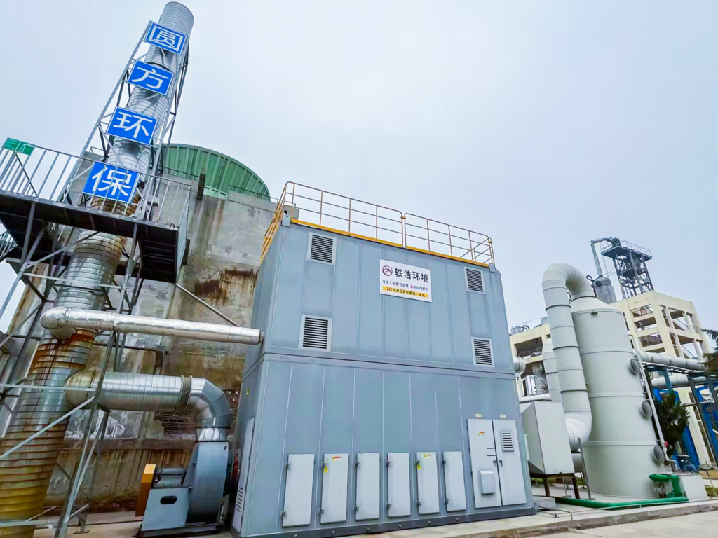
A zeolite rotor concentrator is a continuous-rotation adsorption device that uses a honeycomb-structured rotor impregnated with hydrophobic zeolite as the adsorbent medium. The rotor is divided into three functional zones:
- Adsorption Zone (typically 70–80% of the rotor face): The process exhaust enters at ambient temperature (20–40°C) and passes through the zeolite honeycomb channels. VOC molecules are selectively adsorbed onto the hydrophobic zeolite surface while clean air exits to the stack. Typical single-pass removal efficiency in this zone is 90–95%.
- Desorption Zone (10–15% of the rotor face): A small stream of heated air (180–220°C) flows counter-current through a narrow sector of the rotor, stripping the adsorbed VOCs from the zeolite. This produces a concentrated VOC stream with concentrations 5–20 times higher than the original exhaust. The desorption air volume is typically only 5–10% of the total treated airflow.
- Cooling Zone (5–10% of the rotor face): After desorption, the rotor sector passes through a cooling section where ambient or cooled air restores the zeolite to adsorption temperature before it re-enters the adsorption zone. The cooling air, now preheated, is often recycled into the desorption air stream to improve thermal efficiency.
The rotor rotates continuously at 2–6 revolutions per hour, enabling uninterrupted operation. The key advantage: by concentrating a 200–500 mg/m³ VOC stream into a 2,000–5,000 mg/m³ stream, the downstream oxidizer can operate autothermally—meaning the combustion of VOCs itself generates enough heat to sustain the reaction without continuous auxiliary fuel input.
Catalytic Combustion Technology
Once the VOC-laden desorption air leaves the rotor, it enters the catalytic combustion unit. Unlike thermal oxidation, which requires temperatures of 760–870°C, catalytic oxidation operates at a significantly lower temperature range of 250–400°C by employing noble metal or transition metal oxide catalysts to accelerate the oxidation reaction:
CₓHᵧ + O₂ → CO₂ + H₂O (catalyzed at 250–400°C)
Catalyst Types and Selection
- Noble Metal Catalysts (Pt, Pd on Al₂O₃ or ceramic honeycomb): Highest activity, effective at temperatures as low as 220°C, excellent for mixed VOC streams. More expensive but longer service life (3–5 years). Preferred for pharmaceutical and fine chemical applications where VOC compositions vary.
- Transition Metal Oxide Catalysts (CuO/MnO₂, Co₃O₄, perovskite-type): Lower cost, good resistance to chlorine and sulfur poisoning. Suitable for paint booth exhaust and printing applications. Operating temperature typically 300–400°C.
- Regenerative Catalytic Oxidation (RCO): Combines a catalyst bed with ceramic heat recovery media. The flow direction reverses periodically, achieving thermal recovery efficiencies of 95% or higher. Best suited for very low-concentration streams (below 500 mg/m³ pre-concentration) where autothermal operation is marginal.
Critical Design Parameters
- Space Velocity (GHSV): Typically 10,000–20,000 h⁻¹ for noble metal catalysts, 8,000–15,000 h⁻¹ for metal oxides. Higher space velocity reduces catalyst volume and capital cost but decreases conversion efficiency.
- Catalyst Bed Temperature: 280–350°C for noble metals, 320–400°C for metal oxides. A preheater (electric or gas-fired) is required for cold starts; once autothermal operation is achieved, the preheater is modulated or shut off.
- VOC Inlet Concentration to Catalyst: Must remain below 25% of the lower explosive limit (LEL) for safety. The concentrated stream from the rotor is typically 1,000–5,000 mg/m³, well within safe limits. An LEL monitor with automatic dilution damper control is standard safety equipment.
System Integration and Key Design Parameters
Integrating the zeolite rotor with the catalytic oxidizer requires careful matching of flow rates, concentrations, and thermal balance. Below are the primary design considerations:
Concentration Ratio Optimization
The concentration ratio (Cr) is defined as the ratio of VOC concentration in the desorption outlet to the inlet process exhaust concentration. Typical Cr values range from 5:1 to 20:1. A higher Cr means a smaller oxidizer and lower fuel consumption, but it also means higher desorption temperature and potential zeolite degradation. Most industrial systems target Cr = 10:1 to 15:1.
For a typical case with 80,000 Nm³/h of process exhaust at 300 mg/m³ total VOCs: the desorption air volume is set at 8,000 Nm³/h (10% of total), the theoretical Cr is 10:1, and the concentrated stream enters the catalytic oxidizer at approximately 3,000 mg/m³. The heat released from VOC oxidation at this concentration is sufficient to sustain the catalyst bed at 300–350°C with minimal auxiliary fuel.
Zeolite Rotor Sizing
- Face velocity: 1.5–3.0 m/s through the rotor. Lower velocities improve adsorption efficiency but increase rotor diameter and cost.
- Rotor thickness: 300–500 mm. Thicker rotors provide more adsorption capacity and better concentration ratios, but increase pressure drop (typically 150–350 Pa across the adsorption zone).
- Rotation speed: 2–6 rph. Lower speeds give higher concentration ratios but risk breakthrough in the adsorption zone. Higher speeds reduce concentration but improve safety margins.
Energy Balance and Heat Recovery
The catalytic oxidizer exhaust gas exits at 300–400°C and contains significant thermal energy. A well-designed system incorporates a gas-to-gas heat exchanger to preheat the desorption air using the oxidizer exhaust, reducing the desorption heater load by 40–60%. In RCO configurations, ceramic media heat exchangers can achieve thermal recovery exceeding 95%, making the system nearly autothermal even for very low-concentration VOC streams.
Industry Applications and Case Study
Application Matrix
- Automotive Paint Booths: Large air volumes (100,000–500,000 Nm³/h), VOC concentrations 100–500 mg/m³. Zeolite rotor + RCO is the industry standard, achieving destruction efficiencies >98%. Payback periods of 2–3 years are typical when replacing direct-fired thermal oxidizers.
- Printing and Packaging: Exhaust from gravure and flexographic printing contains solvents (ethyl acetate, toluene, MEK). Concentrations 500–2,000 mg/m³. The rotor + CO combination handles these moderate concentrations efficiently; if inlet concentrations already exceed 2,000 mg/m³, a standalone catalytic oxidizer without the concentrator may be more economical.
- Pharmaceutical and Fine Chemical Synthesis: Batch processes produce variable VOC composition and flow rates. The system must accommodate turndown ratios of 10:1 or more. Variable-frequency drives on the process fan and adjustable rotor speed control are essential design features.
- Semiconductor and Electronics: Low-concentration VOC emissions (50–200 mg/m³) from wafer fabrication and cleaning. Requires ultra-high removal efficiency (>99%). Zeolite rotor concentration plus RCO is often paired with a downstream polishing activated carbon bed.
Case Study: Automotive Parts Coating Facility
A tier-1 automotive parts manufacturer in eastern China operated three spray booths generating a combined exhaust flow of 180,000 Nm³/h with an average VOC concentration of 280 mg/m³ (primarily xylene, butyl acetate, and toluene). The existing direct-fired thermal oxidizer consumed approximately 85 Nm³/h of natural gas, with an annual fuel cost exceeding USD 320,000.
The retrofit installed a zeolite rotor concentrator (4.2 m diameter × 400 mm thick, hydrophobic Y-type zeolite) with a concentration ratio of 12:1, reducing the oxidizer inlet flow to 15,000 Nm³/h at 3,360 mg/m³ VOCs. The catalytic oxidizer used a Pt/Pd honeycomb catalyst with a design space velocity of 15,000 h⁻¹, operating at 300°C. A gas-to-gas plate heat exchanger preheated the desorption air to 150°C before entering the electric heater, reducing the desorption heating load by 55%.
Results after 18 months of operation:
- VOC destruction efficiency: 97.8% (tested quarterly by third-party stack testing)
- Natural gas consumption: reduced to 12 Nm³/h (86% reduction), used only for cold startup and low-load periods
- Annual energy cost savings: USD 275,000
- System payback: 2.4 years
- Catalyst activity: maintained at >90% of initial after 18 months, with annual catalyst cleaning (compressed air blow-down)
- Non-methane hydrocarbon (NMHC) stack emissions: consistently below 30 mg/m³, well under the local regulatory limit of 60 mg/m³
O&M Best Practices
Daily Monitoring
- Pressure Drop Across Rotor: Baseline adsorption zone ΔP should be established during commissioning (typically 150–350 Pa). An increase of >20% from baseline indicates particulate fouling or zeolite degradation. Schedule compressed air backflushing if ΔP trend rises.
- Desorption Temperature Profile: Monitor inlet and outlet desorption air temperatures. A declining outlet temperature at constant heater power suggests zeolite hydrophobicity loss or channel blockage.
- Catalyst Bed Temperature: A gradual decline in the temperature rise across the catalyst bed (ΔT = T_out – T_in) indicates catalyst deactivation. Normal ΔT is 50–80°C for a well-functioning bed at design VOC loading.
- VOC Outlet Concentration: Continuous FID or PID monitoring at the stack. An upward trend in outlet concentration without changes in inlet conditions signals either rotor breakthrough or catalyst degradation.
Preventive Maintenance Schedule
- Weekly: Inspect rotor drive motor and bearing temperature; check desorption heater element continuity; verify LEL monitor calibration with span gas.
- Monthly: Clean pre-filters on the process air intake (particulate accumulation on the zeolite surface is the most common cause of performance decline); inspect catalyst bed surface for dust accumulation or hot spots; verify all damper actuator stroke ranges.
- Quarterly: Perform VOC destruction efficiency test (portable FID at inlet and outlet); analyze catalyst activity via CO conversion test; inspect rotor seal integrity (leakage between adsorption and desorption zones must be <3%).
- Annually: Full rotor inspection including zeolite wash-coat adhesion testing; catalyst sampling and laboratory activity analysis; replacement of rotor drive belt and desorption heater contactors; comprehensive stack emissions testing by accredited third party.
Common Failure Modes and Troubleshooting
- Zeolite Hydrophobicity Loss: Caused by exposure to high-humidity exhaust (>80% RH) without adequate pre-conditioning, or by acidic gas attack on the zeolite framework. Symptoms: reduced concentration ratio, higher outlet VOC concentration. Mitigation: install a dehumidification pre-treatment stage; maintain desorption temperature above 180°C to prevent condensation.
- Catalyst Poisoning: Halogenated compounds, organosilicon vapors, and heavy metals (Pb, Hg, As) irreversibly poison noble metal catalysts. Symptoms: declining ΔT across catalyst bed, increasing outlet VOC. Mitigation: install a guard bed (activated carbon or sacrificial catalyst) upstream of the main catalyst; thoroughly audit all chemicals used in the process for catalyst poisons.
- Rotor Seal Leakage: Wear on the circumferential and radial seals allows untreated air to bypass the adsorption zone or desorption air to contaminate the treated stream. Symptoms: outlet VOC concentration higher than predicted at given inlet conditions. Mitigation: quarterly seal inspection; replace seals when leakage exceeds 3% of design flow.
Regulatory Compliance Considerations
In major industrial markets, VOC emission standards continue to tighten:
- China (GB 37824-2019, GB 16297): NMHC emission limit of 60 mg/m³ for coating and printing industries, with some provinces (Jiangsu, Guangdong) enforcing 40 mg/m³ limits. Destruction efficiency must be ≥97% for systems treating >10,000 Nm³/h.
- EU (IED 2010/75/EU): BAT-AELs for surface treatment using solvents require VOC emissions below 20–50 mg C/Nm³ depending on the sector. Continuous emission monitoring is mandatory for facilities above 10 tonnes/year solvent consumption.
- US EPA (40 CFR Part 63 – NESHAP): MACT standards for various source categories require 95–98% control efficiency. Title V permits require continuous parameter monitoring of oxidizer temperature (or catalyst bed inlet temperature).
The zeolite rotor + catalytic combustion system, properly designed and maintained, can meet all of the above standards with comfortable margins—typically achieving outlet concentrations of 10–30 mg/m³ NMHC.
Total Cost of Ownership
For a 100,000 Nm³/h system treating 300 mg/m³ VOCs, approximate cost benchmarks:
- Capital cost: USD 500,000–800,000 for the complete system (rotor, CO/RCO unit, ductwork, controls, installation). RCO configurations add 20–30% to the CO base cost.
- Annual operating cost (electricity + natural gas): USD 45,000–80,000, compared to USD 300,000–500,000 for a direct-fired thermal oxidizer handling the full flow.
- Catalyst replacement: USD 25,000–50,000 every 3–5 years (noble metal) or USD 10,000–20,000 every 2–3 years (metal oxide). Catalyst cost is a relatively small component of TCO.
- Zeolite rotor service life: 8–12 years with proper maintenance. Rotor replacement cost is approximately 15–20% of initial system capital cost.
- Typical payback vs. direct-fired TO: 1.5–3.5 years, driven primarily by fuel savings.
Conclusion
The zeolite rotor concentrator + catalytic combustion combination represents the most energy-efficient, regulatory-compliant approach for treating large-volume, low-to-moderate concentration VOC streams across a wide range of industries. The technology is mature, with decades of operational data supporting design parameters and reliability expectations. Key to project success is thorough characterization of the VOC stream composition (especially catalyst poisons), careful integration of the rotor and oxidizer thermal cycles, and a disciplined preventive maintenance program. With tightening global emission standards and rising energy costs, the economic case for this combined system becomes stronger every year—particularly for facilities currently operating direct-fired thermal oxidizers or those facing new VOC control mandates.
For inquiries about VOC abatement system design or to discuss your specific industrial exhaust requirements, contact Yfep@yf-ep.com | www.xxyuanfang.cn